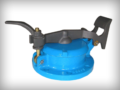
The Pressure & Vacuum Breather Valve should be mounted on tank roof nozzles as close as possible to the tank roof, to ensure that pressure under the pallet is maintained within 3% of the tank pressure.
A range of steel adaptor flanges is available for nonstandard drilling on tank nozzle flange and for use where tank flanges differ dimensionally for valve flanges.
- indicate the position of both the pressure and vacuum pallets, when tank and atmospheric pressure are equal. i.e. both pallets are fully seated.
- shows the position of both pallets, as set pressure is reached, with escaping vapour lifting the pressure pallet and holding the vacuum pallet closed.
- shows the position of both pallets, as set vacuum is reached, with atmospheric pressure lifting the hinged vacuum pallet to allow ingress of air into the tank, whilst holding the pressure pallet closed.
Tables 1 and 2 indicate flow rates for Open Vent Pressure & Vacuum Breather Valves (2" to 12") in both cubic feet per hour and cubic meters per hour, of standard air.
COMBINED UNITS Pressure & Vacuum Breather Valves can be fitted in combination with Flame Arresters.
Note - This type of Installation reduces valve flow capacities and thus special sizing calculations are applicable. (See Table 3)
Pressure & Vacuum Breather Valves can be supplied in a range of alternative materials for chemical and/or cryogenic services and can be used with air dryers fitted at the vacuum inlet port, to protect those products which could be adversely affected by normal atmospheric air. It is suitable for wide range of services in the petroleum, chemical and related industries for land tankages only.
Blow-down is the difference between opening and closing pressures.
The floating diaphragm operation ensures that blowdown is minimised to 10% for pressure relief and 10- 15% for vacuum relief.
shows capability of the resilient diaphragm to wrap around the edge of the pallet seat. The high ratio of seating force to seating area provides a tight seal. As the pressure or vacuum rises, the relevant pallet begins to lift, but the diaphragm wrap around at the edge of the seat maintains a good seal. As the pressure or vacuum continues to rise, the pallet lifts further, but the diaphragm naturally assumes a good seal. When pressure or vacuum reaches the set conditions, the pallet opens fully.

